

Nerf Stryfe Simple Modification Tip2021-10-09
The NERF guns have also a big knowledge. I was pulled into the nerf world by a colleague. I happened to be a student of engineering. The soldering iron, circuit, SOP, BGA and other chips can also be soldered and blown, so my colleague pulled in to help change the blaster.
At present, NERF guns are roughly divided into two types: manual and electric. The several types of electric guns in production are flywheel powered. As the name suggests, they are squeezed out by rotating two flywheels. The first thing to do is a stryfe, an entry nerf blaster for beginners.
Here's one thing to add, NERF's guns are divided into orange machine (orange trigger) and gray machine. The range of the US version of the orange machine is about 7 meters longer than that of the China's gray machine. Spring guns are because of different springs. Electric guns have different motors and different resistances (some say they are inductance, I agree with this statement, and the influence of inductance on the range is negligible), so I won’t discuss it here, just talk about me. Changed.
First of all, the air protection and electric protection are empty bullet protection, that is, no bullets do not allow the trigger to be pulled. The empty protection is to prevent the stick during continuous shooting. To put it bluntly, it is to be cool; the electric protection is to limit the voltage to protect the motor. , In order to increase the range, generally use four lithium ferrite batteries, 3.3V x 4 = 13.2V, to remove the varistor on the electrical protection module.
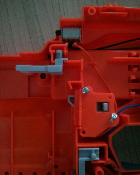
The gray L-shaped plastic on the top is the empty ammo protection, remove it! The gray part where there are two screws below is protected by an empty clip, that is, the trigger cannot be pulled without a clip.
Disassemble the empty clip like this:
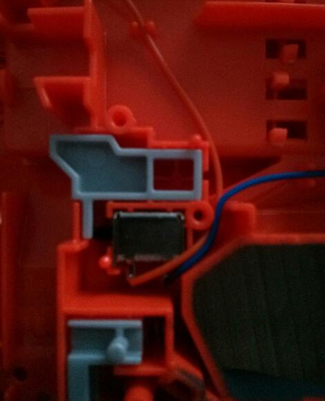
It looks like this after dismantling, compare it with:
The micro switch at the top of the picture above is the protection of the magazine clearing

The original wire was too thin. When I changed it for the first time, I added an extra wire because I didn’t have any materials on hand. Later it was changed to a single thick wire.
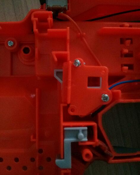
The picture below is the electric insurance
This is the removed pressure sensitive, you can also twist the pressure sensitive and just short the two feet.
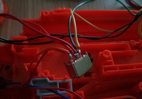
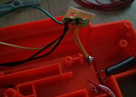
Changed two-line micro switch for magazine clearing room
Motor body

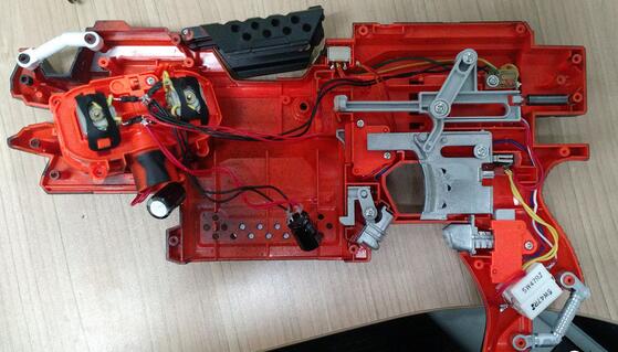
Overall picture.
The above is the basic modification, and the following is the beginning.
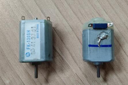
First of all, we need to change the motor. How to choose the motor?
The left of the picture is FK-130SH, and the right of the picture is the original motor. FK-130SH is a little thicker than the original, so you need to grind the motor compartment.
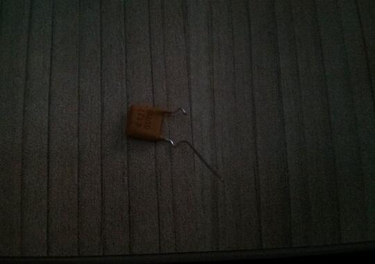
The picture below shows the resistors and capacitors I bought at jack Ma's store
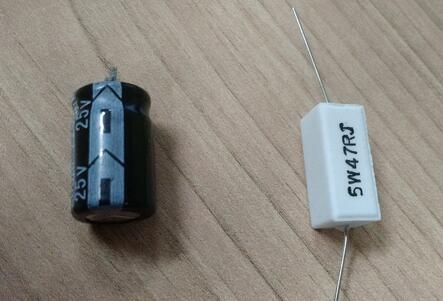
In order to facilitate the understanding of zero-based people, I will briefly talk about the principle. The resistor plays a role of partial voltage and current limiting in this circuit, allowing the motor to maintain a low speed during standby operation, reducing the initial speed of full acceleration, reducing acceleration pressure and Noise during acceleration. The capacitor plays the role of energy storage, so the original author calls it a big pond to help the motor accelerate when it accelerates at full speed.
The whole firing process is like this, pull down the original acceleration switch, the motor runs at low speed, pull the trigger, the trigger triggers the micro switch or leaf switch (the micro switch I chose, the micro switch is stronger and more expensive than the blade, although I am in Free from the market), the micro switch short-circuits the resistance, the motor voltage is instantly raised, accelerates with full force, the pond is discharged, the motor is at the highest speed, the trigger is pulled to the end, and the bullet is fired.
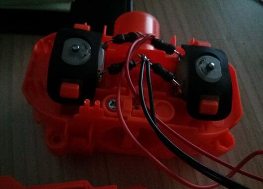
I removed the 4 inductors between the motors. The inductance is to suppress the current change too fast, and it feels that it conflicts with the role of the pond. I removed them, but still kept the flame retardant piece. In addition, because the motor was changed, the two resistors were connected in parallel. The resistance is still too large, so I connected 4 resistors of this specification in parallel. The picture below is how I changed it
- Company Info
- About Us
- Contact Us
- Customer Reviews
- Blogs
- Brands
- YouTube Videos
- User Center
- FAQ
- Forget Password
- My Orders
- Tracking Order
- My Account
- Register
- Affiliate
- Company Policy
- Locations We Ship To
- Payment Methods
- Shipping Policy
- Refund Policy
- Privacy Policy
- Terms of Service
- Disclaimer
- Contact Us
Shanghai zhenduo electronic technology Co,.ltd
Address: 15 Changyi Road, Shanghai, China
USA address: 818, colorado Springs, the United States
Phone number: +86 021-315970888
Email address: qq463301085@gmail.com